INSTALLTION INSTRUCTIONS
QUICK-STRUT® INSTALLTION INSTRUCTIONS (FRONT/REAR) MODULAR REPLACEMENT ASSEMBLY

QUICK-STRUT® INSTALLTION INSTRUCTIONS
(FRONT/REAR) MODULAR REPLACEMENT ASSEMBLY
- Read this instruction sheet and any additional instruction sheets, plus any instructions printed on the parts package carefully prior to removing the strut from the vehicle.
- Do not grip polished piston rod with any tool. Nicks or scratches will cause decreased service life.
- Part number on unit may differ from part number on carton. This unit is correct for the vehicle.
WARNING
- This unit is gas pressurized, do not heat or open.
- Always wear safety glasses for eye protection.
- Use safety stands whenever a procedure requires you to be under the vehicle.
- The complete old modular assembly (Fig. 5, 6 & 7) should be discarded in a safe manner. The coil spring is under high tension. Keep away from children. Disassembly should not be attempted. Follow the enclosed instruction sheet to avoid injury.
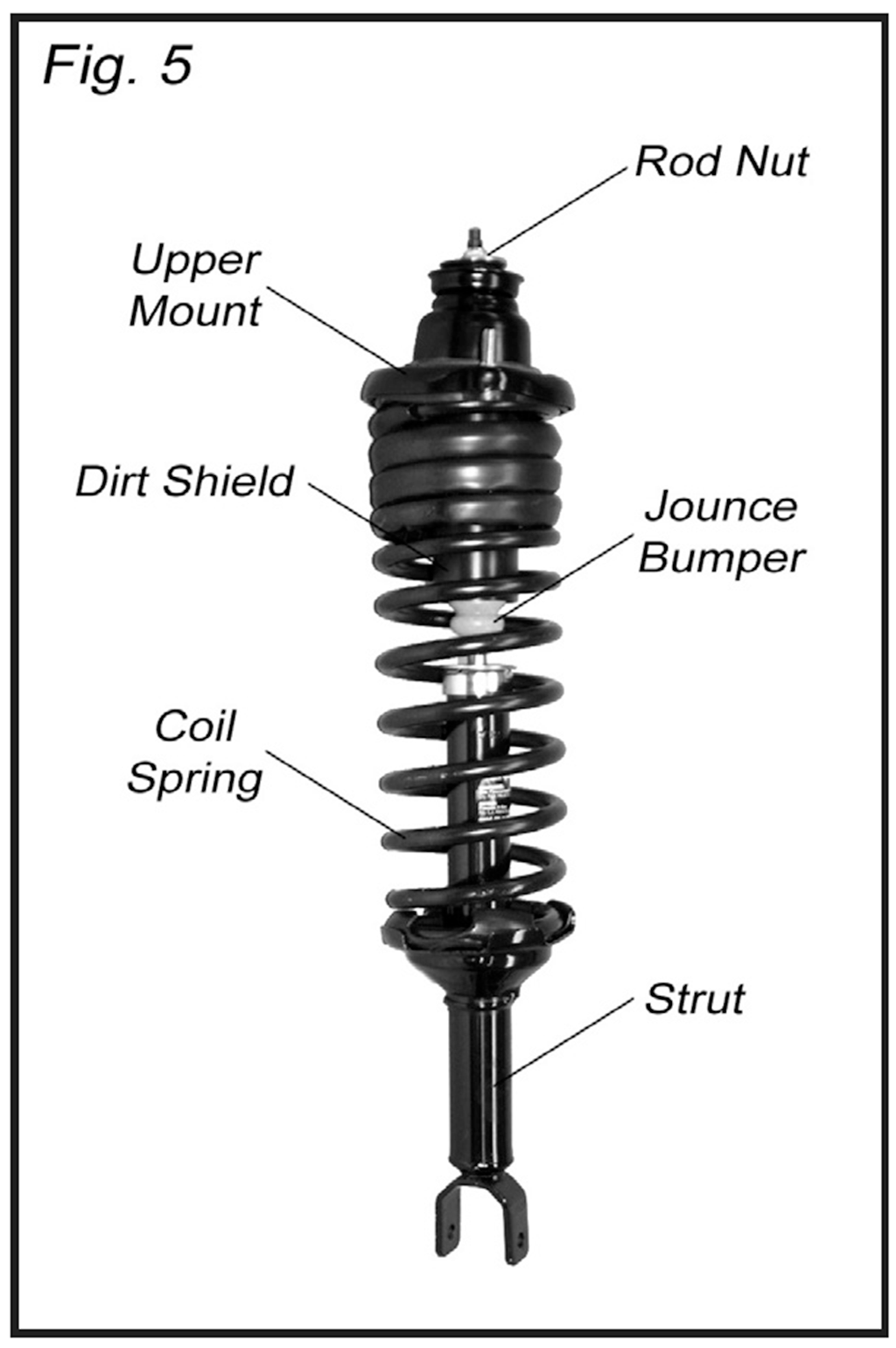
- The Quick-Strut rod is already fully extended so disregard the note on the enclosed instruction sheet to extend rod. Never remove the rod nut (B) (Fig. 1) as serious injury could result from sudden release of coil spring tension.
- New coil springs will return your vehicle to it’s original height. On older vehicles this may initially appear high. Allow a settling period for the springs to reach their new final height.
- It is suggested to verify the vehicle height prior to installation of the Quick-Struts.
REMOVAL PROCEDURE
(See additional instruction sheet included for more clarification on removal process.)
- (Fig. 1) Locate and loosen, but do not remove, the bearing plate’s upper mounting nuts (A). Mark one of the upper retaining studs in relation to strut tower for orientation and transfer the mark to the appropriate Quick Strut upper mounting plate stud.
- Raise the vehicle and support the frame. Remove the (front/rear) wheels.
CAUTION: Make sure the vehicle is properly supported!
•
Remove brake hose bracket, stabilizer link, and ABS retainer or nuts from strut,
if so equipped. Save bolts and nuts for re-use.
•
Cover drive shaft boot with a boot protector to avoid damage. Retain the half-shaft with wire to prevent from over-extension and possible damage to the drive shaft or mechanisms.
•
(Fig. 4) Remove and save nut (J) from outer tie rod end, if so equipped,
and disconnect tie rod end from strut. (Steering arm struts only.)
ONE LOWER BOLT STYLE:
•
(Fig. 2) Remove and save the pinch bolt (C) and nut (D) that retain the lower end of the strut housing.
•
(Fig. 3) Remove and save the spindle-to-strut assembly pinch bolt (E). Using a large screwdriver slightly spread strut-to-spindle pinch joint, if required, for removal. Tap on top surface of spindle (F) with a hammer to drive it down and
off the end of the strut assembly.
FORM 01069 Rev. 10/15
INSTRUCTIONS
QUICK-STRUT® INSTALLATION INSTRUCTIONS
(FRONT / REAR) MODULAR REPLACEMENT ASSEMBLY
© 2015 Tenneco
TWO LOWER BOLTS STYLE:
•
(Fig. 4) Remove and save lower mounting nuts (G) and bolts (H). Separate lower strut mount from steering knuckle.
•
(Fig. 1) Remove and save the bearing plate upper mounting nuts (A).
(P-Pack included with new nuts.)
•
Remove the strut assembly from vehicle (Fig. 5, 6 & 7).
CAUTION: SPRING IS UNDER HIGH COMPRESSION LOAD WHEN INSTALLED. ATTEMPTS TO REMOVE SPRING WITHOUT PROPERLY RESTRAINING THIS LOAD MAY RESULT IN INJURY. NEVER REMOVE THE ROD NUT (B) (FIG.1)
AS SERIOUS INJURY COULD RESULT FROM SUDDEN RELEASE OF THE
COIL-SPRING TENSION.
INSTALLATION PROCEDURE
•
Reposition the strut assembly on the vehicle and install the upper mounting nuts. Hand-tighten two upper mount nuts three full turns (A) (Fig. 1). NOTE: Rotation of the upper bearing plate may be necessary to align mounting studs (Fig. 7 for example) with the holes in the vehicle frame. Some Quick-Strut units do not rotate and are fixed (171845, 171781 and 171880, for example).
ONE LOWER BOLT STYLE:
•
Install pinch bolt (C) loosely (Fig. 2). Raise the lower control arm with jack until the vehicle lifts slightly off the safety stand. Tighten the pinch bolt to the value shown in the original equipment service manual.
•
Install strut assembly into spindle pinch joint. Push or tap spindle assembly onto strut and remove screwdriver from pinch joint opening. Install spindle-to-strut assembly pinch bolt into spindle and through strut (Fig. 3). Torque bolt (E) to the value shown in the original equipment service manual.
•
Obtain replacement bolts if threads are bent or damaged.
TWO LOWER BOLTS STYLE:
•
Install lower mounting nuts (G) and bolts (H) (Fig. 4). Torque nuts to the value shown in the original equipment service manual.
STANDARD INSTRUCTIONS:
•
Install tie rod end to strut (Fig. 4) and torque nut (J) to the value shown in the original equipment service manual.
•
If vehicle is equipped with stabilizer bracket, install stabilizer link to strut and torque bolt to the value shown in the original equipment service manual.
•
Install brake hose and ABS brackets to strut, if so equipped. Torque bolt to the value shown in the original equipment service manual.
•
Remove boot protector from drive shaft. Remove temporary wire retainer, if used.
•
Replace wheels and torque lug nuts to manufacturer’s specifications.
Lower vehicle.
•
Tighten bearing plate’s upper mounting nuts (A) (Fig. 1) to the torque value shown in the original equipment service manual. Torque only with tires on the ground.
•
After installation, with vehicle on the ground, torque rod nut (B) (Fig. 1) to the value shown in the original equipment manual.
•
Align front end to vehicle manufacturer’s specifications.
•
Check and reset rear wheel toe to specifications, if required.
Refer to manufacturers recommended settings.
CAUTION: DO NOT OVER-TIGHTEN NUTS OR BOLTS. EXCESSIVE TORQUE CAN DAMAGE THE THREADS ON THE NUT OR BOLT